What are Bandpass Filters
TECHNICAL INFORMATION
Bandpass filters are one of the simplest and most economical ways to transmit a well-defined band of light, and to reject all other unwanted radiation. Their design is essentially a thin film Fabry-Perot Interferometer formed by vacuum deposition techniques, and consists of two reflecting stacks, separated by an even-order spacer layer. Each one of these structures is referred to as a cavity, and some filters may contain as many as eight cavities. There are many different variations of the Fabry-Perot type bandpass filter, but for this catalog, we will only consider the all-dielectric and metal-dielectric type.
The all-dielectric type consists of two highly reflecting mirrors separated by a dielectric spacer layer. These reflecting mirrors are constructed of alternating high and low refractive index materials and the reflectance of the stack is sometimes in excess of 99.99%. By varying the thickness of the spacer layer and or the number of reflecting layers, one can alter the central wavelength and bandwidth of the filter. This type of filter displays very high transmission in the passband, but, has a limited range of out-of-band blocking. To compensate for this deficiency, an additional blocking component is added, which is either all-dielectric or metal-dielectric depending upon the required blocking range. This additional blocking component will eliminate any unwanted out-of-band radiation but it will also reduce the overall throughput of the filter.
The metal-dielectric type is similar to the all-dielectric type except that it utilizes a metal spacer layer instead of a dielectric layer. Although this type of filter has excellent out-of-band blocking and high passband transmission, it lacks the sharp cut-on and cut-off slopes of the typical two and three cavity filters. The metal-dielectric type is mainly used for bandpass filters in the ultraviolet. However one version, the induced transmission type, is used as an additional blocking component when rejection is required to the far infrared.
Wavelength Shift With Angle Of Incidence
The central wavelength of the all-dielectric Fabry-Perot filter will shift lower in wavelength with an increase in the incident angle. The amount of wavelength shift is dependent upon the incident angle and the effective index (N*) of the filter. This feature can be very useful in tuning a narrowband filter to the desired central wavelength. The following formula may be used to determine the wavelength shift of a filter in collimated light with incident angles up to 15 degrees:
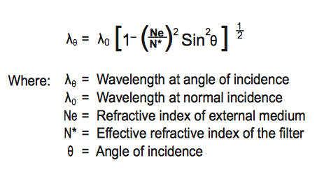
When a filter is used with non-collimated light such as convergent or divergent rays, the wavelength shift will appear somewhat less than that of collimated light at the same angle. In a cone of light only the central ray is normal to the surface and all others are increasingly off-angle. The resultant shift could be given by integrating the wavelength shift over the range of angles but this is a rather lengthy process. A good approximation of the shift can be made by using the previous formula and dividing the calculated shift by two. This will work in systems where the full cone angle is a maximum of 20°.
Wavelength Shift With Temperature
The center wavelength of an interference filter will shift linearly with changes in ambient temperature, therefore it is very important to specify the operating temperature when ordering. The wavelength shifts in the direction of the temperature change, up with a positive change and down with a negative change. This shift factor will vary depending upon the filter's initial center wavelength. Please refer to the following chart for the proper temperature coefficient.
To reduce the chance of damage due to thermal shock, we recommend a maximum operating temperature of 70°C, and a maximum temperature change of 5°C per minute.

Bandshape
Due to the fact that the Fabry-Perot filter is essentially Lorentzian in shape, the cut-on and cut-off slopes are very shallow and the rate of attenuation in the out-of-band blocking range is very slow. To improve the slopes and increase the attenuation in the blocking band, we introduce more cavities into the construction. Please refer to the following charts for a comparison of one to four cavity filters and note that this data is only applicable to dielectric bandpass filters.
Another very important factor to note is that due to matching the different cavities within a filter construction, we cannot add an infinite amount of cavities. Please refer to the and custom interference filter section of this catalog for the appropriate information.
Environmental Stability
All of our bandpass filters are stabilized to prevent drift of peak wavelength with age and are hermetically sealed for maximum humidity protection. Each filter is mounted in a black anodized aluminum ring which affords increased protection against damage resulting from rough handling and moisture penetration. However, even with this construction, it is advisable to avoid prolonged exposure to environments in which high humidity and large temperature variations are concurrent.
Bandpass Filter Orientation
As a general rule, the highly reflective side of the filter should always face the source of radiation. This minimizes the thermal load on the absorbing glass blocking components and epoxies, thereby extending the lifetime of the filter. Apart from reduction of thermal effects, filter orientation is without influence on the spectral characteristics.
What are Bandpass Filters Summary
The effects of temperature, optical path geometry and environmental conditions must be considered when selecting or specifying bandpass filters. All of our filters are designed to operate at 23°C in normal incidence collimated beams. Please consult with one of our technical sales representatives before specifying any off-normal conditions so that a filter best suited for your application can be designed.